Control Plane
Introduction
The SCION control plane is responsible for discovering path segments and making them available to endpoints. This includes path-segment exploration (also called “beaconing”), registration, lookup, and finally the combination of path-segments to end-to-end paths.
The control service is responsible for the path exploration and registration processes in the control plane. It is the main control-plane infrastructure component within each SCION AS. The control service of an AS has the following tasks:
Generating, receiving, and propagating Path Construction Beacons (PCBs). Periodically, the control service of a core AS generates a set of PCBs, which are forwarded to the child ASes or neighboring core ASes. In the latter case, the PCBs are sent over policy-compliant paths to discover multiple paths between any pair of core ASes.
Selecting and registering the set of path segments via which the AS wants to be reached.
Managing certificates and keys to secure inter-AS communication. Each PCB contains signatures of all on-path ASes. Every time the control service of an AS receives a PCB, it validates the PCB’s authenticity. When the control service lacks an intermediate certificate, it can query the control service of the neighboring AS that sent the PCB.
Path Segments
As described previously, the main goal of SCION’s control plane is to create and manage path segments, which can then be combined into forwarding paths to transmit packets in the data plane. SCION distinguishes the following types of path segments:
A path segment from a non-core AS to a core AS is an up-segment.
A path segment from a core AS to a non-core AS is a down-segment.
A path segment between core ASes is a core-segment.
So each path segment either ends at a core AS, or starts at a core AS, or both.
Note
There are no SCION path segments that start and end at a non-core AS. However, when combining path segments into an end-to-end SCION path, shortcuts and peering-links can be used.
All path segments are reversible: A core-segment can be used bidirectionally, and an up-segment can be converted into a down-segment, or vice versa, depending on the direction of the end-to-end path. This means that all path segments can be used to send data traffic in both directions.
Path Exploration (Beaconing)
Path exploration is the process where an AS discovers paths to other ASes. In SCION, this process is referred to as beaconing.
In SCION, the control service of each AS is responsible for the beaconing process. The control service generates, receives, and propagates path-segment construction beacons (PCBs) on a regular basis, to iteratively construct path segments. PCBs contain topology and authentication information, and can also include additional metadata that helps with path management and selection. The beaconing process itself is divided into routing processes on two levels, where inter-ISD or core beaconing is based on the (selective) sending of PCBs without a defined direction, and intra-ISD beaconing on top-to-bottom propagation. This division of routing levels is a key architectural decision of SCION and important for achieving a better scalability.
Inter-ISD or core beaconing is the process of constructing path segments between core ASes in the same or in different ISDs. During core beaconing, the control service of a core AS either initiates PCBs or propagates PCBs received from neighboring core ASes to other neighboring core ASes. Core beaconing is periodic; PCBs are sent over policy-compliant paths to discover multiple paths between any pair of core ASes.
Intra-ISD beaconing creates path segments from core ASes to non-core ASes. For this, the control service of a core AS creates PCBs and sends them to the non-core child ASes (typically customer ASes). The control service of a non-core child AS receives these PCBs and forwards them to its child ASes, and so on. This procedure continues until the PCB reaches an AS without any customer (leaf AS). As a result, all ASes within an ISD receive path segments to reach the core ASes of their ISD.
On its way, a PCB accumulates cryptographically protected path- and forwarding information per traversed AS. At every AS, metadata as well as information about the AS’s ingress and egress interfaces are added to the PCB.
Origination of PCBs
Every core AS originates PCBs at regular intervals, and sends these to all egress interfaces to connected neighbor ASes. An originated PCB sent to a neighboring core ASes initiates an inter-ISD beacon, ultimately resulting in a core-segment. An originated PCB sent to a child AS initiates the intra-ISD beacon creating an up/down segment.
Propagation of PCBs
PCBs are propagated at regular intervals at each AS. When PCBs are received, they are not propagated immediately, but put into temporary storage until the next propagation event. The selection and propagation of PCBs differs between the inter-ISD and intra-ISD beacon schemes.
Core ASes implement the inter-ISD / core beaconing scheme. For every interface connecting to a neighboring core AS:
Select the best \(N\) PCBs for each origin core AS. This can take into account both the available PCBs as well as local policies and information about the link to the neighbor.
Extend the selected PCBs by adding an AS entry
Send the extended PCBs over the interface
Non-core ASes implement the intra-ISD / non-core beaconing scheme. For every interface connecting to a child AS:
Select the best \(N\) PCBs. This can take into account both the available PCBs as well as local policies and information about the link to the child AS.
Extend the selected PCBs by adding an AS entry
Send the extended PCBs over the interface
AS Entries
Every AS adds a signed AS entry to the PCBs it originates, propagates or registers.
This AS entry includes the relevant network topology information for this AS-hop defined by the ingress and egress interface IDs of the beacon. The so-called hop field includes a MAC that authorizes the use of this hop in the path segment defined by the PCB, until it expires. See the description of the SCION Path in the data plane section for more details on the hop field format and the MAC chaining mechanism.
Additionally, an AS entry can contain metadata such as the link MTU, geographic locations of the AS routers, latencies, etc.
For illustration, the following code blocks show the definition of the protobuf message definitions for the AS entry “body” and the contained hop field information. This is just a small excerpt of the relevant definitions. See the SCION Control Plane IETF draft (section “Components of a PCB”) for a more complete discussion of the message formats and signature inputs, or proto/control_plane/v1/seg.proto for the raw protocol definitions used in this project.
message ASEntrySignedBody {
    // ISD-AS of the AS that created this AS entry.
    uint64 isd_as = 1;
    // ISD-AS of the downstream AS.
    uint64 next_isd_as = 2;
    // The required regular hop entry.
    HopEntry hop_entry = 3;
    // Optional peer entries.
    repeated PeerEntry peer_entries = 4;
    // Intra AS MTU.
    uint32 mtu = 5;
    // Optional extensions.
    proto.control_plane.v1.PathSegmentExtensions extensions = 6;
}
HopEntry, referred to
in the ASEntrySignedBody definition above.message HopField {
// Ingress interface identifier.
uint64 ingress = 1;
// Egress interface identifier.
uint64 egress = 2;
// 8-bit encoded expiration offset relative to the segment creation
// timestamp.
uint32 exp_time = 3;
// MAC used in the dataplane to verify the hop field.
bytes mac = 4;
}
Peering Links
PCBs do not traverse peering links. Instead, available peering links are announced along with a regular path in the individual AS entries of PCBs. If both ASes at either end of a peering link have registered path segments that include a specific peering link, then it can be used to during segment combination to create an end-to-end path.
Registration of Path Segments
Path registration is the process where an AS transforms selected PCBs into path segments, “terminating” them by adding a final AS entry with a zero egress interface, and adds these segments to the relevant path databases, thus making them available for the path lookup process.
As mentioned previously, a non-core AS typically receives several PCBs representing path segments to the core ASes of the ISD the AS belongs to. Out of these PCBs, the non-core AS selects those down-path segments through which it wants to be reached, based on AS-specific selection criteria. The next step is to register the selected down-segments with the control service of the core AS that originated the PCB.
Intra-ISD Path-Segment Registration
Every registration period (determined by each AS), the AS’s control service selects of PCBs to transform into path segments:
Up-segments, which allow the infrastructure entities and endpoints in this AS to communicate with core ASes. Up-segments are registered in the local path database of the AS.
Down-segments, which allow remote entities to reach this AS. Down-segments are registered, via a remote-procedure call, in the path-segment database of the core AS that originated the PCB. As a result, a core AS’s path database contains all down-segments registered by their direct or indirect customer ASes.
Core Path-Segment Registration
The core beaconing process creates PCBs from core AS to core AS. Every registration period, the AS’s control service selects sets of PCBs to turn into path segments and register. These selected core-segments are added to the local path database of the core AS that created the segment (i.e. the one at the end of the beacon chain), so that local and remote endpoints can obtain and use these core-segments. In contrast to the down-segment registration procedure, there is no need to register core-segments with other core ASes (as each core AS will receive PCBs originated from every other core AS).
Path Lookup
An endpoint (source) that wants to start communication with another endpoint (destination), needs up to three path segments:
An up-path segment to reach the core of the source ISD
a core-path segment to reach
another core AS in the source ISD, in case the destination AS is in the same source ISD, or
a core AS in a remote ISD, if the destination AS is in another ISD, and
a down-path segment to reach the destination AS.
The process to look up and fetch path segments consists of the following steps:
First, the source endpoint queries the control service in its own AS (i.e., the source AS) for the required segments. The control service has up-path segments stored in its path database.
The control service in the source AS queries the control services of the reachable core ASes in the source ISD, for core-path segments to core ASes in the destination ISD (which is either the local or a remote ISD). To reach the core control services, the control service of the source AS uses the locally stored up-path segments.
The control service then queries the control services of the remote core ASes in the destination ISD, to fetch down-path segments to the destination AS. To reach the remote core ASes, the control service of the source AS uses the previously obtained and combined up- and core segments.
Finally, the control service of the source AS returns all retrieved path segments to the source endpoint.
The endpoint combines all path segments into an end-to-end path
All remote path-segment lookups by the control service are cached.
On SCION end hosts, a SCION daemon is usually employed to do the path-lookup on behalf of applications. This SCION daemon also caches path-segment lookup results.
Segment Type |
Responsible control service(s) |
|---|---|
Up-segment |
Control service of the source AS |
Core-segment |
Control service of core ASes in source ISD |
Down-segment |
Control service of core ASes in destination ISD (either the local ISD or a remote ISD) |
Path-Segment Combination
The last step of the path-resolution process is to combine the available up, core and down path segments to end-to-end forwarding paths. This path-segment combination process is done by each endpoint separately. Typically, end hosts run the SCION daemon which centralizes the path-resolution process and returns fully formed end-to-end paths to applications. However, applications could also choose to bypass the daemon and perform the path-resolution directly.
The figures below illustrate the various ways in which segments can be combined to form end-to-end paths. See the description of the SCION Path for the specifics on how these end-to-end paths are encoded in the packet header.
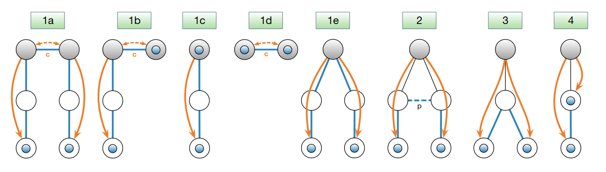
Combination of path segments to paths: the blue circles represent the end hosts; the shaded gray circles represent core ASes, possibly in different ISDs; blue lines without arrow heads denote hops of created forwarding paths; the dashed blue line denotes a peering link (labeled “p”); orange lines with arrows stand for PCBs and indicate their dissemination direction; dashed orange lines represent core beacons exchanged over core links (labeled “c”). All created forwarding paths in cases 1a-1e traverse the ISD core(s), whereas the paths in cases 2-4 do not enter the ISD core.
See also
- SCION Overview
Introduction to the SCION architecture and core concepts.
- Data Plane
Description of SCION packet header formats and processing rules for packet forwarding based the packed-carried forwarding state.
- IETF Draft SCION Control Plane
Formal description and specification of the SCION control plane.